 |
| November 13, 2012 | Volume 08 Issue 42 |
Designfax weekly eMagazine

Archives
Partners
Manufacturing Center
Product Spotlight
Modern Applications News
Metalworking Ideas For
Today's Job Shops
Tooling and Production
Strategies for large
metalworking plants
Engineer's Toolbox:
The evolution of non-contact accurate motion
Non-contact linear and rotary position measurement is attainable with robust multipole magnets.
By Steven Gauthier, P.E., Dexter Magnetic Technologies, Elk Grove Village, IL
Introduction
As the world's demand for robust and reliable technology continues to increase, there is also the increased need for accurate, repeatable, and reliable measurement of linear and rotary motion and positioning. From the Assyrians in ancient Mesopotamia to cog railways in the 1800s, the manner in which motion designs have reacted to market needs has continued to develop.
Pairing electrical and mechanical techniques for linear and rotary motion is one means that has advanced motion. The robust nature of mechanics and the flexibility of electrics can allow for highly dynamic and accurate linear and rotary systems. Of course, cost and resources are always influencing factors upon designs. The attractiveness of life-cycle costing and plug-and-play options is becoming more apparent as motion designs work to achieve the optimum level of performance with the minimal amount of investment.
With costs and time an ever-increasing influence on industry designs, engineers looking for position measurement systems have sought out cost-effective alternatives. Applications for this technology include monitoring the movement of linear shafts and pistons, rotating gears and wheels, pivoting joints, and basically the motion of any one mechanical component in a piece of equipment relative to another. Applications can be as small as miniaturized focus modules for biometric ID, to the motions controls for a CNC gantry type coordinate measuring machine. As varied as the applications are, so are the markets. Industries employing accurate positioning measurements systems include aerospace, oil and gas exploration, semiconductor manufacturing, automotive, military, and medical.
Contact or no-contact options for linear and rotary position measurement
The options that system engineers are presented with to measure their linear and rotary motion is quite varied. There are two distinct types of measurement: contact and non-contact. Contact systems are exactly that -- they require contact to measure the motion. Conversely, the non-contact systems do not require this. Examples of contact systems include potentiometers and mechanical proximity switches. Non-contact means of measurement include optical/lasers, magnetostrictive, capacitive, inductive, and ultrasonic principles.
There are benefits for both means that depend on the application requirements. Applications with the requirements of long life and high reliability should select the non-contact means of operation. This is due in part to the limited component wear and degradation. Non-contact options limit damage that may occur from contact with a work piece and offer the added security of allowing for measuring systems to be encapsulated or potted, protecting them from the operational environmental conditions.
The overarching benefit of a non-contact measuring system is the potential high degree of accuracy that the design is capable of achieving. When selecting a system for accuracy, engineers come to expect that the higher the system accuracy, the higher the price of the system. The positive correlation of pricing and accuracy is a legacy for measurement systems that has become the leading disadvantage for using a non-contact system: the high costs.
Weighing cost versus benefit is needed to determine whether the system will fit the application and how necessary the accuracy is in the overall design. Recognizing that there is a gap in the market for highly accurate and also highly cost-effective systems, advances in non-contact designs have been made. New magnet strip technology allows for cost-effective linear and rotary positioning measurement systems with all the benefits of traditional non-contact systems, including optimal accuracy.
For a deep dive into an example of non-contact positioning system, a look at Hall cell technology offers such an option. The Hall-Effect principal was discovered by physicist Edwin Hall in 1879 (Figure 1). He discovered that when an electrical conductor or semiconductor with current flowing through it in one direction was subjected to a magnetic field perpendicular to the direction of the current flow, a voltage could be measured across the conductor at a right angle to the current path.
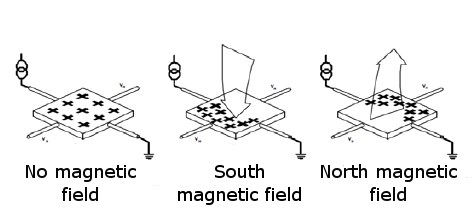
Figure 1: Hall-effect principle.
This induced voltage has three key characteristics. First, its strength is proportional to the strength of the current in the conductor and to the strength of the magnetic field passing through the conductor. Second, the change in the induced voltage with changes in the current and magnetic field strength is repeatable. Lastly, this phenomenon is measurable. This basic principle can be applied to the development of a low-cost, non-contact sensor to measure linear and rotary motion. In use, to measure the movement of one location, surface, or component relative to another, a Hall sensor is attached to one location and a magnet is attached to the other. As the two change location position relative to each other (either linear or rotary), this change is directly measured by the change in the induced voltage across the Hall sensor. This measurement is achieved in a completely non-contact environment.
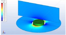
Unlike traditional non-contact systems, one of the limitations of measuring linear position with Hall sensors is the limited range and accuracy of measurement due to limitations in the magnetic field of a "traditional" bipole axially or diametrically magnetized magnet with a single North and South pole (Figures 2 and 3). The strength of the magnetic field of this sized bipole magnet drops below the required minimum for sensor manufacturers. For example, a standard for AMS, a leading manufacturer of multipole Hall sensors, states that magnetic strength needs to be maintained within 15 to 20 mm from the surface of the magnet, depending upon the specific magnet used. To increase linear measurement distance and accuracy when using a Hall sensor, a magnet with multiple North/South poles with very precise pole lengths is needed.
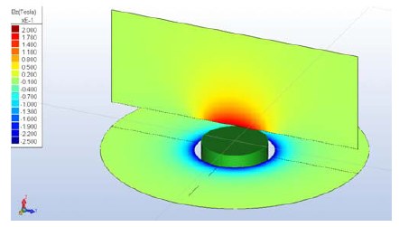
Figure 2: Magnetic field of an axially oriented magnet.
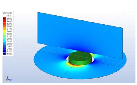
Figure 3: Magnetic field of a diametrically oriented magnet.
This knowledge has led to the development of a multipole magnet that would fulfill the market requirements for accuracy, cost, and field strength in a continuous pattern of repeating North and South poles (Figure 4). The inherent design of the multipole magnet makes the length of linear measurement capable only limited by the length of magnet that can be physically made.
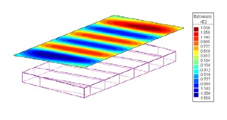
Figure 4: Magnetic field of a multipole strip magnet.
Multipole magnet evolution
The development of highly accurate, low-cost, linear and rotary position measurement systems not only required development into the multipole magnets but also an analysis and development of the Hall sensors that utilize the magnets. Looking at the research and development that would be needed, Dexter Magnetic Technologies partnered with Austriamicrosystems (AMS) for the Hall sensors. Dexter's expertise is grounded in magnetic materials and the science behind magnetic attraction. AMS was selected as a partner for the Hall sensors because the company has developed a family of non-contact, high-resolution magnetic encoders for accurate linear and off-axis rotary sensing. The AMS sensors offer a measurement resolution of down to <0.5 micron. A multipole strip magnet or ring magnet with a pole length of 1.0 mm, 1.2 mm, or 2.0 mm (length is dependent upon sensor selection) is required for the sensor to operate properly.
There are several requirements of these magnets for an overall measurement system to be successful. First, the magnets must be made of a material that can be magnetized to sufficient field strength to meet the requirements of the Hall sensors. Secondly, they must also be made of a material that can be tailored to different lengths. The length of linear measurement is limited by the length of the magnet, so a magnet that can be easily modified for different lengths is needed. Lastly, and perhaps the most important requirement, is that the magnetizing process must result in a highly accurate and repeatable pole length.
To initiate the development, Dexter Magnetic Technologies finalized the following specifications for a multipole strip magnet:
- Pole lengths of 1.0 mm, 1.2 mm, or 2.0 mm;
- Pole length accuracy within 2.0% of a pole pair (40 um for a 1.0-mm pole length).
The next step in the development process was to investigate the different materials that could be used to produce the magnets according to the rather unique specification mentioned above. Analyses on several materials were made, with a final selection being a flexible ferrite material with an Energy Grade of 1.4 MGOe that exhibited the required characteristics for proper magnetizing as well as the ability to alter the length options. The use of a flexible ferrite material to produce the magnets allows for the production of very long magnets, up to 5,000 mm or longer. It was also decided that the magnets were to be designed and constructed in such a way that allowed for a cost-effective end component.
When the testing phase of the product cycle occurred, two standard sizes were developed and tested. Looking at the popularity of the AMS Hall sensor options on the market, two multipole strips were tested. The first multipole unit was 1.5 mm thick by 9.5 mm wide. The second multipole unit was 0.76 mm thick by 3.18 mm wide. Both magnets were able to be magnetized to produce a 10-mT field at 1.0 mm. They met the AMS sensor requirement of a magnetic field strength range at the surface of the sensor of 5 mT to 60 mT. The operating temperature of the magnet ranged from -40 degrees C to 80 degrees C and a Linear Coefficient of Thermal Expansion of 5 x 10⁻⁵ * c-1.
Analysis into the proper means of mounting the magnets resulted in both magnets being able to perform to the required technical specifications while being mounted with a pressure-sensitive adhesive applied to the nonmagnetized side. This configuration allowed for the mounting of the magnet on a range of surface materials and textures. A 3M Double Coated Paper Tape 410M was selected as having the required properties for a wide range of applications.
The targeted test parameters of the multipole magnet were accuracies of better than 40 microns. Testing of multipole magnet strips to such stringent standards had never before been performed. It became apparent during the testing phase that a new test fixture would have to be developed to ensure accurate results (Figure 5). To accomplish this, a custom test fixture was designed and fabricated to begin initial validations of the 1.0-mm pole-length magnet design.
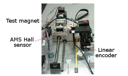
Figure 5: Test fixture.
Because Dexter had developed and tested magnets of different materials and strengths previously, the testing of the multipole product followed a similar process. The magnet to be tested was mounted on a small sample platform at a designated distance below a Hall sensor, which was attached to a carriage that moved linearly by means of a stepper motor. To measure the linear movement of the magnet along the test fixture during testing, an optical encoder was used. This included a linear scale with graduations attached to the base of the testing fixture. A readhead that provided required resolution was used to precisely measure movement of the test platform and the magnet being tested along the linear scale. An AMS NSE5310 Hall sensor was used to measure the magnetic field of the test magnet and its linear position as the sample platform moved along the testing fixture. The NSE5310 is a high-resolution magnetic linear encoder that provides instant indication of the magnet position with a resolution of 0.488 microns per step (12 bit [4,096] over a 2.0 mm pole pair).
Initial testing results showed measurements of greater than 2% accuracy, which were higher than expectations. Analysis into the test fixture highlighted improvements that needed to be made to the device. After needed tooling improvements were made, standard 2% accuracy results were achieved (Figure 6).
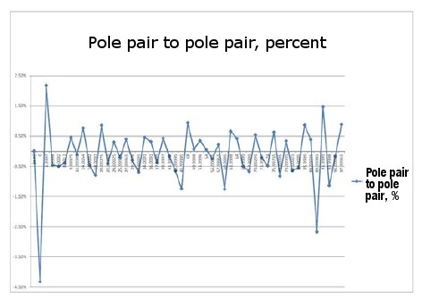
Figure 6: Multipole Magnet Test Results.
Testing also showed the need for proper placement of end effects to ensure appropriate travel distance during application. To achieve optimal accuracy in desired travel distance as highlighted above, the end effects needed to be removed from the overall length of the multipole magnet strip. Adding the additional 2 mm needed for end effects to the overall length increased the length needed when specifying overall motion.
What the future will bring
With investment into new fixtures and continual development into the multipole magnet product, new tests are scheduled to be conducted for the longer pole lengths.
Assessing current multipole usage shows that with appropriate application, required accuracy for non-contact position measurement can be achieved with minimal customer investment. With the multipole magnet strip as a cost-effective and easy-to-install partner to the AMS Hall sensor, the era of achieving accurate linear and rotary motion with cost-effective measurement sensing has arrived.
Want more information? Click below.
Published November 2012
Rate this article
View our terms of use and privacy policy